
Builders Of Longest Cable-Stayed Bridge In Japan Recap Construction At Kick-Off Session Of Civil Engineering Expo

 The longest cable-stayed bridge in the world—the Tatara Bridge in Japan which opened in May of this year—was the topic of one of the kick-off session at this year's premier of the Civil Engineering Conference and Exposition. The event, which will run until Oct.19, is expected to draw more than 1,000 attendees and is sponsored by the American Society of Civil Engineers in Charlotte, NC.
Engineers from the Japan Society of Civil Engineers as well as representatives from the Honshu-Shikoku Bridge Authority and Mitsubishi Heavy Industry Ltd. spoke at length on the new testing techniques and technologies, which were incorporated over the course of the six-year construction of this record-setting bridge. Until the opening of the Tatara Bridge, the longest cable-stayed bridge had been the Normandie Bridge in France, which checks in at 856m.
The completed length of the Tatara Bridge is 1480 m long and is composed of a center span of 890 m flanked by two unusually short side spans, required by the peculiar topography, measuring 270m and 320m each.
Analysis indicated cable-stayed bridge superior to suspension one
Originally, back in 1973 when the project was first conceived, the bridge was designed as a suspension bridge due to its long center span. However, according to Shuichi Suzuki, an engineer with the Honshu-Shikoku Bridge Authority, this plan would have entailed a large excavation of a steep hill to set the anchorage on one of the connecting islands—Ikuchijima Island—which was located in a national park. Since technological advances, both in long-span bridge technology and computer-based structural analysis, had occurred since the original plans were made, a cable-stayed bridge was considered in 1989 and decided upon
Several factors were considered before this decision was made. Characteristics of cable-stayed bridges compared with suspension bridges with center spans ranging from 500 m to 2,000 m were carefully studied. The three main factors considered included the aerodynamic design, the eventual cost and the ultimate impact upon the natural environment. In all three instances, the cable-stayed bridge was superior.
Additional considerations that needed to be taken into account included the area's propensity for high winds (three typhoons struck during the actual construction of the bridge) and large scale earthquakes. The geological conditions (primarily granite) were also a factor making a bridge preferable to a tunnel.
Aerodynamic comparisons between cable-stayed and suspension bridges
Aerodynamic studies between the cable-stayed and suspension revealed:
• Horizontal displacement: It was found the horizontal wind-induced displacement in a cable-stayed bridge is almost the same as that in a suspension bridge with center spans up to 1,100 m. A cable-stayed bridge suffers larger displacement for center spans exceeding 1,100 m indicating the horizontal displacement factor was not prohibitive as long as the center span remained shorter than 1,100 m.
• Bending and torsional frequency: Tests reveal the natural frequency of bending and torsional oscillation decreases as the center span increases in both a cable-stayed and a suspension bridge. It was noted that a cable-stayed bridge has a higher torsional frequency than a suspension bridge and, therefore, generally offers better aerodynamic stability than a suspension bridge with the same span length.
• Steel weight: The total weight of the steel in the superstructure (cables, girders, and towers) is almost the same in the two options when span length is less than 1,000 m.
Thus, it was concluded that a cable-stayed bridge was the better option as long as the center span remained shorter than 1,000 m.
Extensive testing and analysis characterized project throughout
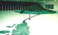
One of the highlights of the project was the extensive testing and analysis that accompanied the progress of the bridge. Wind tunnel tests were conducted at a large wind tunnel laboratory managed by the bridge authority. First, a full-model wind tunnel test with a scale of 1/70 was conducted. It was noted that attempts were made to make the scale model as large as possible. The unique topography of the area also prompted a full-model test including models of the mountainous topography surrounding the bridge. That scale was 1/200.
Wind tunnel tests conducted during construction as well as completion
 Since safety of the project during construction as well as at completion was important, wind tunnel tests were conducted in both instances. Tests were made on the two towers in both a completion and erection stage. These precautions were rewarded with a perfect safety record of no accidents during the entire six-year construction phase.
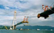 Of particular interest was the finding that the aerodynamic stability of the towers during erection was effected by scaffoldings. When the erection scaffolding in the tower top was removed from the tower shafts, galloping vibration on first bending mode was induced. In reproducing scaffolding used during erection, galloping vibration did not occur at an average wind velocity of 90 m/s or less. As a result, scaffolding contributed to stabilization of the galloping. It was determined that the increase in the draw coefficient of the tower shaft, the turbulence intensity of the wind, and the axial flow were possible reasons for the suppression of the galloping vibration. As a result, in spite of the fact that the tower is 220 meters tall and no damping devices were installed, aerodynamic stability of the tower was secured when all scaffoldings were attached. The integrity of the precautions was proven on three occasions when typhoons hit during construction with no mishap.
Other factors tested throughout the project included the girder buckling and elastic support, the tower shape and the cable design.
Of particular interest were the cables, which were installed in a fan shape with two planes of 21 rows of cables fixed to each side of the towers. The 168 cables were made of semi-parallel wire strands consisting of galvanized wires 7 mm in diameter covered with polyethylene tubing. The longest cables consisted of 379 wires, were 460 m long and had a diameter of 169 mm.
Special cable surface used to improve aerodynamic stability
To counteract "rain vibration," a typical wind-induced cable vibration associated with wind and rain, the cable surface was indented or "dimpled" to improve aerodynamic stability. This was the superior method determined after also testing two other methods which included connecting the cables with wires or increasing the logarithmic damping of the cables by installing damping devices between cables and girders. Both of these methods had disadvantages related to the durability of the connection wires and to the structural details/maintenance of damping devices.
 Two aerodynamic countermeasures of mitigating the vibration by processing the surface of the cable surface included "protuberance cable" and "indented cable." The latter was chosen due to its lesser drag coefficient.
Another questions concerned the length of construction, which the builders noted was particularly long due to the necessity to draw the financing from various sources. Future bridges should be built in less time, the builders said.
 An inquiry was made also as to whether or not the construction costs could be cut due to the extensive time-consuming and "money-consuming" testing that had already been done with the Tatara project. The answer was that it was hoped that much information will profit future projects, but testing will still need to be done. "The analyses were not perfect (for all instances)," the builders noted, "and additional wind tunnel tests will be necessary."
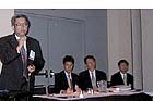
Other presenters at the meeting included: Koji Kawaguchi with the bridge authority and Masaharu Shigetome with Mitsubishi.
Moderating the presentation was Kazuhiko Kawashima, professor, department of civil engineering, Tokyo Institute of Technology. He may be contacted for more details at kawasima@cv.titech.ac.jp.
By Joyce Jungclaus, Editor, Public Works Online